

1 Introduction
One of the major advancements in membrane technology is the addition of inorganic materials (fillers) in polymer matrix to form mixed-matrix membranes (MMMs) [1]. This can improve the membrane's gas separation performance as the inorganic fillers are able to modify the gas transport properties of the membrane [2]. Conventional fillers such as zeolite, carbon molecular sieve, and silica have been commonly used because of their excellent intrinsic properties, such as defined pore structures which could enhance gas selectivity. Besides that, metal oxides such as MgO and TiO2 have also been incorporated because of their nanoscale size that has a higher interfacial area for adhesion with the polymer matrix per unit volume. Owing to their high specific area, particles' distribution in the polymer matrix was enhanced and formation of nonselective voids at the polymer-filler interface was prevented [2]. In a study conducted by Moradihamedani et al. [3], TiO2 nanoparticles (0 wt % to 7 wt %) were added into polysulfone (PSf) polymer matrix to form MMM. Based on the findings, homogeneous nanoparticle distribution were achieved at a lower loading of TiO2 (≤3 wt %), but agglomeration of TiO2 which resulted in microvoid formation was observed beyond 5 wt % TiO2 loading. In addition, MMM with higher TiO2 loading showed higher thermal stability. For the gas separation performance, the incorporation of TiO2 nanoparticles showed optimum permeance and selectivity between 3 wt % and 5 wt % loading. Based on their findings, the usage of metal oxides as inorganic fillers in MMMs still possesses some limitations. The agglomeration of nanofillers in the polymer matrix appears to be an important challenge faced in the fabrication of MMMs. Owing to the small size of nanoparticles, they often have very high surface activity. As a result, the particles tend to gather and form aggregates to create aggregates of micron size. This lowers their surface energy so that their stability in the polymer matrix can be increased. Titanium (IV) oxide, TiO2, is one of the nanoparticles that were widely used in the manufacturing of nanocomposite membranes. Hence, TiO2 precipitation often occurs at higher loading when preparing MMMs, leading to the formation of nonhomogeneous TiO2 in MMMs. Owing to the agglomeration of fillers, nonselective defects such as large pinholes and macrovoids which cannot be reached by polymer segments are produced in the MMM. These defects in the polymer matrix would deteriorate the gas separation performance as permeability of the membrane increases drastically with no selectivity.
Recently, emerging inorganic fillers such as graphene and polyhedral oligomeric silsesquioxane (POSS) have been studied because of their potential to enhance the gas transport properties of MMMs. Graphene, a type of carbon nanomaterials, can be used to replace carbon nanotubes (CNTs) because of its outstanding electrical, thermal, structural, and mechanical properties. On the other hand, POSS which possesses a unique cage structure and nanoscale diameter (1–3 nm) has also received interests among researchers. POSS consists of a caged hybrid framework with inorganic and organic constituents, Rn(SiO1.5)n, where R represents the organofunctional group [4]. Owing to the organic constituents of POSS which provides resin compatibility, it can be easily incorporated into the polymer matrix. Besides that, these organic functionalities can form bonds such as van der Waals forces, covalent bonds, or hydrogen bonds with various fillers, thus enhancing polymer-filler compatibility.
In the development of the MMM, particle dispersion and distribution remain a major challenge to advance the membrane fabrication technology. The filler particles' dispersion and distribution can have significant effect on the mechanical properties and gas separation performance of MMMs because of the changes in the local polymer chain [5]. Conventionally, dispersion analyses were conducted qualitatively through transmission electron microscopy (TEM), scanning electron microscopy (SEM), or optical microscopy (OM) images. However, qualitative research often gathers data through visual representation rather than measurements. The collected data are analyzed in a subjective manner which could lead to wrong conclusions drawn from the research conducted. For qualitative research, it requires the input from the research point of view when analyzing the data collected, which could lead to lack of transparency and problem of generalization. Limited quantitative analyses were implemented to study the filler particles' dispersion in MMMs.
These quantitative analyses include the uniform distribution characterization tool (e.g., d-metric) and interparticle distance characterization tool (e.g., free-space length, Lf). In the d-metric method, filler particles are ideally spaced as far apart as possible at a uniform distance within a polymer matrix, as shown in Fig. 1 (a). Therefore, the size of the unreinforced region is minimized and the polymer-particle interfacial area is maximized. Nevertheless, filler particles often form clusters and aggregates when dispersed in polymer matrix, as shown in Fig. 1 (b). This has resulted in the increase in the size of unreinforced domain and reduced the polymer-particle interfacial area. The d-metric characterization tool is used to measure the average deviation from uniform dispersion based on a quadrant-sampling algorithm in MATLAB. Pfeifer and Bandaru [6] implemented this tool to quantify the dispersion degree of CNTs in epoxy reactive ethylene terpolymer (RET) matrix.
Illustration of particles dispersion showing (a) ideal uniform dispersion and (b) realistic dispersion.
In contrast, the interparticle distance characterization tool measures the maximum distance between the filler particles (i.e., size of unreinforced polymer region). Owing to the absence of filler particles, these unreinforced regions represent the weak link of the membrane and behave as pristine polymer which limits the overall membrane performance. Hence, compared with the d-metric tool, this method provides a more direct measure of filler dispersion. One of the measurements used is known as free-space length, Lf, which is defined as the largest characteristic size of the unreinforced polymer regions. According to Khare and Burris [5], the Lf value decreases when particles distribute more uniformly for a fixed filler loading and size (Fig. 2b). The Lf value also reduces when the filler particle size decreases for a given particle shape and loading (Fig. 2c). For a given particle size and distribution, the Lf value decreases as loading increases (Fig. 2d) [5].
Four types of filler dispersion: (a) random dispersion which has the maximum Lf value. The value of Lf reduces when (b) particles are distributed more evenly at given constant loading and size; (c) Particles' size reduces for a given size and distribution; (d) Filler loading increases for a given size and distribution. Lf represents the square length.
From the aforementioned quantitative characterization tool, both methods have their own limitation and advantages. For the uniform distribution characterization tool (e.g., d-metric), the characterization process is rather simple and straightforward as it only compares the particles' dispersion with a standard uniform distribution. However, this method is unrealistic and only useful for descriptive purposes as it does not measure the distribution of filler particles in a real case scenario. In addition, this technique disregards the effect of particles' density or sparsity of dispersion. On the contrary, the interparticle distance characterization tool (e.g., free-space length, Lf) is simple and sensitive to dispersion state, density, and length scales [5,6]. In the study conducted by Khare and Burris [5], this tool effectively demonstrated the relationship of free-space length with mechanical properties such as tensile modulus and elongation to break. At a larger free-space length, the detrimental effect of agglomeration was more significant.
In this study, the role and effectiveness of a caged hybrid framework as a dispersant for TiO2 is evaluated. The aim of this study is to qualitatively and quantitatively analyze the dispersion degree of TiO2 nanoparticles in the membrane matrix. The MMMs were synthesized via dry-wet phase inversion process. The cross-section morphologies and distribution of titanium elements, quantitative analyses, thermal stability test, and the separation performance for CO2 and CH4 gases were tested for the MMMs.
2 Materials and methods
2.1 Preparation of TiO2-OPOSS/PSf MMM
Asymmetric MMMs were prepared from dope solutions containing octaisobutyl polyhedral oligomeric silsesquioxane (OPOSS; Hybrid Plastics) with a purity ≥99.9%, titanium (IV) oxide (TiO2; Sigma-Aldrich) with a purity ≥99.5%, and polysulfone (PSf; Sigma-Aldrich) with a molecular weight of ∼35,000. The binary solvent used consists of tetrahydrofuran (THF; Merck) and dimethylacetamide (DMAc; Merck). All chemicals were used without purification or modification. The chemical structure of octaisobutyl POSS is depicted in Fig. 3. Before the experiments, different total inorganic fillers loading was tested for both TiO2 and OPOSS which included 6 wt % (3 wt % of OPOSS and 3 wt % of TiO2), 8 wt % (4 wt % of OPOSS and 4 wt % of TiO2), 10 wt % (5 wt % of OPOSS and 5 wt % of TiO2), 12 wt % (6 wt % of OPOSS and 6 wt % of TiO2), and 14 wt % (7 wt % of OPOSS and 7 wt % of TiO2). The optimum total filler loading was found to be 6 wt % (3 wt % of OPOSS and 3 wt % of TiO2) as it has the highest gas separation performance among all. Hence, the total inorganic filler content was maintained constant at 6 wt %. The ratio of OPOSS and TiO2 varied from 0 to 6 wt %, as shown in Table 1.
Molecular structures of octaisobutyl POSS [8]. POSS, polyhedral oligomeric silsesquioxane.
The composition of TiO2-OPOSS/PSf MMMs.
| Sample | Filler content (wt %) | |
| TiO2 | OPOSS | |
| 0/6-T/OPOSS | 0 | 6 |
| 1/5-T/OPOSS | 1 | 5 |
| 2/4-T/OPOSS | 2 | 4 |
| 3/3-T/OPOSS | 3 | 3 |
| 4/2-T/OPOSS | 4 | 2 |
| 5/1-T/OPOSS | 5 | 1 |
| 6/0-T/OPOSS | 6 | 0 |
The MMMs were prepared by using the dry-wet phase inversion method. First, TiO2 and OPOSS were added into 7.5 mL of THF and 2.5 mL of DMAc solvent (73 wt %) at room temperature. To ensure homogeneous dispersion of fillers in the binary solvent, the mixture was stirred and sonicated for 30 min. Subsequently, 3.3325 g (27 wt %) of PSf pellets was added batchwise to improve the interfacial interaction of inorganic fillers within the polymer matrix with continuous stirring at 200 rpm and 50 °C [7]. The solution was continuously stirred to remove trapped microbubbles for 24 h followed by sonication for 4 h. Then, a casting knife with a gap setting of 200 μm was used to cast the resulting dope solution on a leveled glass plate. The membrane was left under convective evaporation for 10 s and immersed in distilled water for 24 h. The membrane instantaneously peeled off from the glass plate and was removed from the water bath after 1 day. The synthesized membrane was dried for 48 h at room temperature before characterization.
2.2 Qualitative characterization
The fabricated membranes were characterized by SEM and energy-dispersive X-ray spectroscopy (EDS). The microscale images of TiO2-OPOSS/PSf MMMs were analyzed by SEM (Hitachi TM 3030 Tabletop Microscope) to evaluate the membrane morphology. After cracking the membranes cryogenically in liquid nitrogen, the samples are sputter coated with platinum or gold at a voltage of 15 kV. The surface and cross sections of MMMs were analyzed to demonstrate the membrane morphology and structure and to detect the existence of TiO2 when fillers were added with magnification between 1200 × and 1500 ×. EDS (Bruker Quantax 70) was used to examine the elements present in the MMMs with magnification between 1000 × and 3000 × at an operating acceleration voltage of 5.00 kV. The dispersion of TiO2 nanoparticles in the membrane matrix was also examined. After the sample was positioned on a sample holder, a focused beam of electrons was bombarded on it. The information on the elemental composition of samples was obtained through the X-ray spectrum emitted.
2.3 Quantitative characterization
MATLAB coding was used to identify the free-space length (Lf) and degree of dispersion (d-metric). Based on the work conducted by Khare and Burris [5], for the EDS images obtained, the pixel values for the filler particles and polymer region were identified and the size of images was adjusted to 500 × 500 pixels using the ImageJ® software. The filler particles in the image are set to black color (pixel value = 0), while the polymer domain, which represents the unreinforced area, is set to white color (pixel value = 255). In the MATLAB algorithm, the threshold value is set to 150 to differentiate the black filler particles from the polymer matrix [5,9]. Then, the converted binary images were inserted into the MATLAB coding to obtain the respective value of free-space length, Lf. First, the fraction of particles was calculated and stored. Then, the code was iterated for 1000 times to compute the mode (the largest possible Lf value where the intersecting particles are zero and have the highest number of occurrence). The code ran in a square size to obtain the largest square possible among the filler particles in which the intersecting particles is the randomly placed square is zero.
Similarly, for the d-metric measurements, the converted binary images obtained from EDS were input into the MATLAB program code. Then, 10,000 randomly placed quadrants would be placed on the inserted binary images. The optimal quadrant size is to be twice the mean area of a filler particle. Later, the MATLAB code generates the d-metric as compared with an ideal distribution or standard distribution of a hexagonal lattice (HEX). Fig. 4 showed the hexagonal pattern which was selected as the uniform pattern. Ten readings of d-metric with respect to the HEX pattern were obtained from the computation, and the standard deviation from 10 measurements was recorded. For an image that has poor dispersion or larger aggregates, the d-metric obtained would have a larger value because of the larger deviation from the uniform standard pattern [6].
Illustration of an equilateral hexagonal lattice which was used as the uniform distribution in MATLAB code.
2.4 Gas separation performance
In terms of membrane separation performance, single-gas permeation tests were carried out on CO2 and CH4 to measure permeance and ideal selectivity of the membrane. Pure CO2 and CH4 gases at a purity of 99.99% and a soap bubble flowmeter were used to calculate the flow rate of gas through the membrane. The gas permeation test was performed at 25 °C and 5 bar. The gas flow rate was calculated by using Eq. (1):
| (1) |
| (2) |
| (3) |
3 Results and discussion
3.1 Qualitative dispersion analyses
Fig. 5 shows the microscopy micrographs of the resultant asymmetric membranes. It can be seen that all of the resultant MMMs have a thin dense selective top layer, finger-like porous substructure extending toward the middle layer, and sponge-like bottom support layer [11]. The dense, finger-like and sponge-like structures were typical of an asymmetric membrane prepared by the phase inversion method [12,13]. The dense layer was obtained because of solidification of polymer dope solution after a short convective evaporation period [11]. The finger-like substructure was obtained because of high solvent and nonsolvent exchange rate between THF/DMAc and distilled water, which resulted in fast precipitation of the polymer. On the other hand, the sponge-like substructure was formed because of delayed solvent and nonsolvent exchange. This is because the precipitated polymer at the top layer obstructed the solvent exchange [13,14]. Mohsenpour et al. [13] also observed similar membrane morphologies when TiO2 was added as additives to Polyvinylidene fluoride (PVDF) polymer. As the content of TiO2 increased from 1 wt % to 6 wt %, it was observed that the finger-like layer extended deeper toward the bottom layer of the membrane. It was hypothesized that owing to the increase in the depth of finger-like structure, the porosity of membrane would increase with increasing TiO2 loading. Besides that, the hydrophilicity of the polymer solution also increased with increasing TiO2 content. This increased the solvent and nonsolvent exchange rates, resulting in a faster phase inversion and ultimately leading to the development of longer interconnecting channels within the membrane matrix [15].
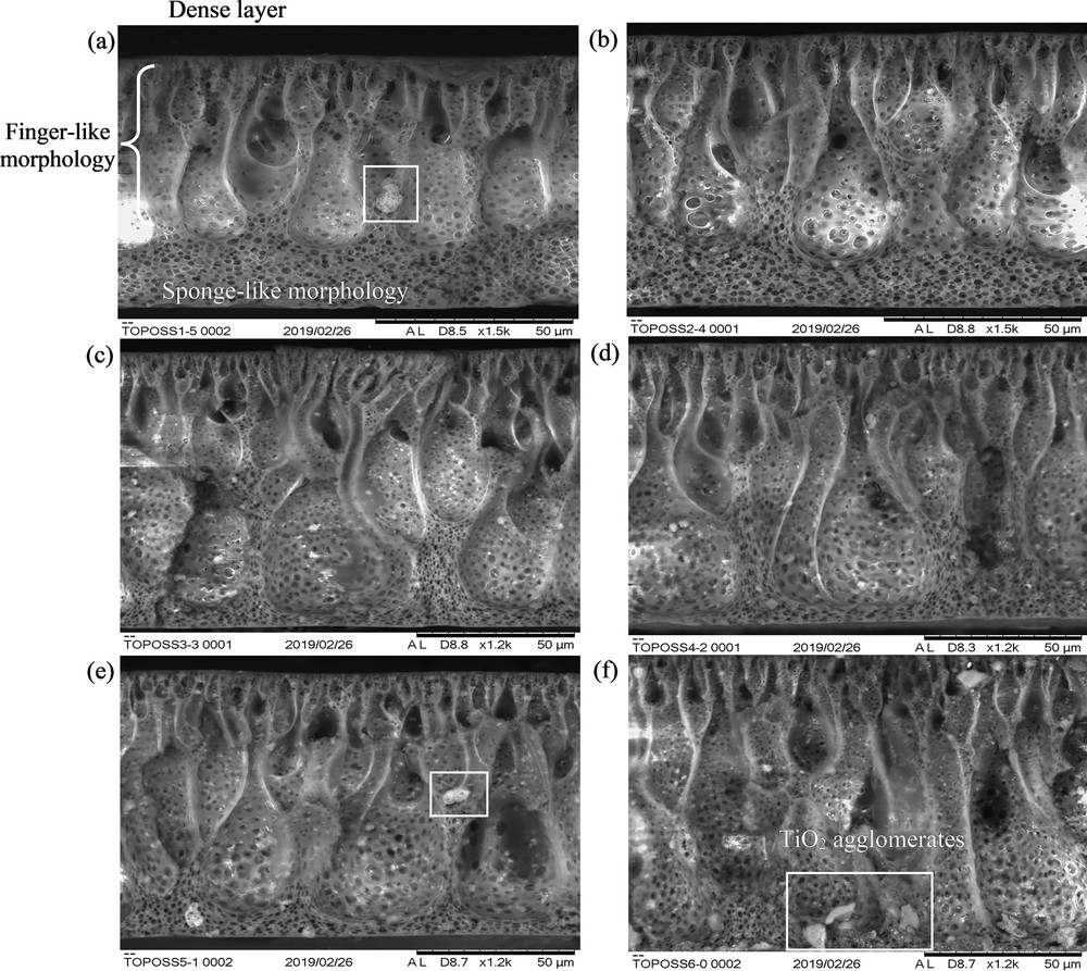
Cross section morphology of (a) 1/5-T/OPOSS, (b) 2/4-T/OPOSS, (c) 3/3-T/OPOSS, (d) 4/2-T/OPOSS, (e) 5/1-T/OPOSS, and (f) 6/0-T/OPOSS MMMs. The white boxes denote the formation of TiO2 agglomerates. MMM, mixed-matrix membrane; OPOSS, octaisobutyl polyhedral oligomeric silsesquioxane.
However, TiO2 precipitates with a larger diameter were observed with increasing TiO2 loading. This was validated by elemental mapping of Ti element, as shown in Fig. 6, wherein TiO2 nanoparticles were found to form microsized agglomerates throughout the membrane matrix. This is due to the attractive van der Waals forces of TiO2 and their high surface energy. Therefore, the nanoparticles clumped together to reduce their surface energy and increase particle stability [16]. When TiO2 loading increased, the entire system was dominated by the attractive van der Waals forces, which led to an increase in TiO2 collision frequency. Hence, the higher the TiO2 loading, the higher the degree of attachment and agglomeration. As the ratio of TiO2 to OPOSS varied from 1 wt % to 6 wt % for TiO2 and 5 wt % to 0 wt % for OPOSS, the agglomeration of TiO2 nanoparticles was found to vary with OPOSS loading, as shown in Fig. 6 (a)–(f). According to Zhou et al. [17], OPOSS acts as a dispersant by reducing the surface energy of TiO2 nanoparticles, causing them to repel one another, thus preventing agglomeration. OPOSS is a caged hybrid framework with isobutyl group at the corner of the cage structure. Hence, the isobutyl group increases the solubility with polysulfone polymer, while the inorganic silsesquioxane cage binds with TiO2 to improve the overall dispersion and distribution of TiO2 [4]. However, the degree of dispersion is highly dependent on OPOSS loading. At optimum OPOSS loading (3/3-T/OPOSS and 4/2-T/OPOSS), it was observed that the TiO2 agglomeration was not severe and the titanium elements were distributed evenly across the membrane matrix. Nevertheless, when OPOSS loading exceeded 3 wt %, large clumps of Ti elements were observed, which signifies unfavorable dispersion of TiO2 nanoparticles. On the other hand, when OPOSS loading was lesser than 2 wt %, TiO2 agglomerates were also found. This was due to the small amount of OPOSS used which could not fully enclose the surface of TiO2. These qualitative analyses were further verified by using the quantitative characterization tool.
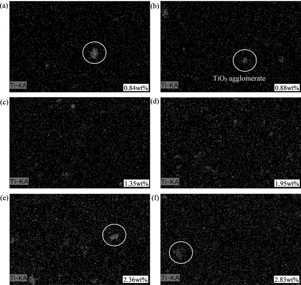
Titanium elemental mapping of (a) 1/5-T/OPOSS, (b) 2/4-T/OPOSS, (c) 3/3-T/OPOSS, (d) 4/2-T/OPOSS, (e) 5/1-T/OPOSS, and (f) 6/0-T/OPOSS MMMs. The white circles denote TiO2 agglomerations. The white boxes denoted the elemental weight percentage of Ti element in the membrane matrix. MMM, mixed-matrix membrane; OPOSS, octaisobutyl polyhedral oligomeric silsesquioxane.
3.2 Quantitative dispersion analyses
Fig. 7 illustrated the bitmap images of MMMs with different loadings of TiO2 and OPOSS. For all the membranes, black color represents the inorganic fillers, while white color demonstrated the unreinforced PSf polymer region. The free-space length (Lf) and d-metric were simulated from Fig. 7 using MATLAB code and are illustrated in Fig. 8. It was found that the particle area fraction increased with increasing TiO2 loading. This means that the fraction of matrix occupied by TiO2 particles increased, which corroborated with the results from Fig. 6.
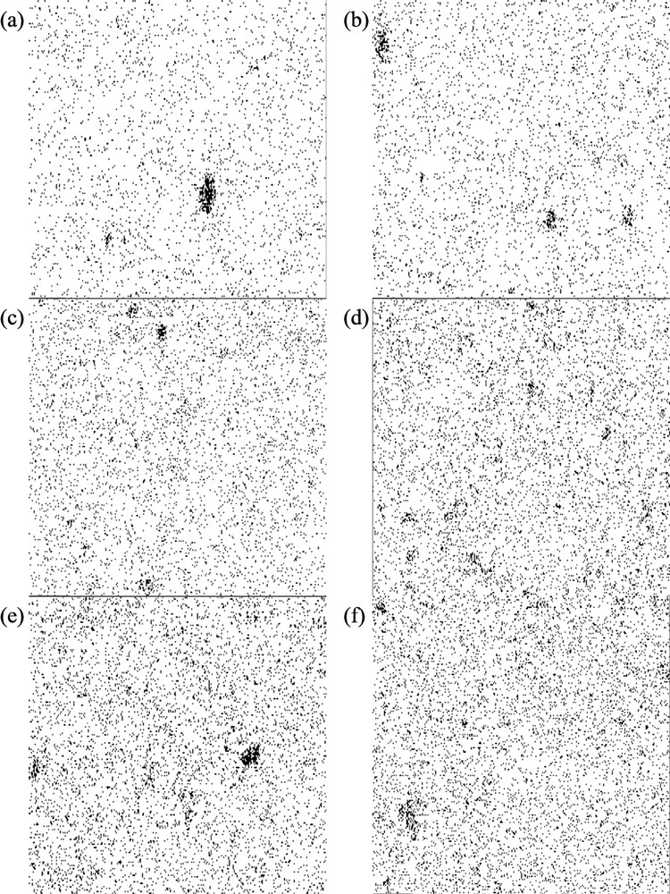
Bitmap images of titanium elemental mapping of (a) 1/5-T/OPOSS, (b) 2/4-T/OPOSS, (c) 3/3-T/OPOSS, (d) 4/2-T/OPOSS, (e) 5/1-T/OPOSS, and (f) 6/0-T/OPOSS MMMs. The black color represents the filler particles, while white area represents the unreinforced polymer region in the membrane matrix. MMM, mixed-matrix membrane; OPOSS, octaisobutyl polyhedral oligomeric silsesquioxane.
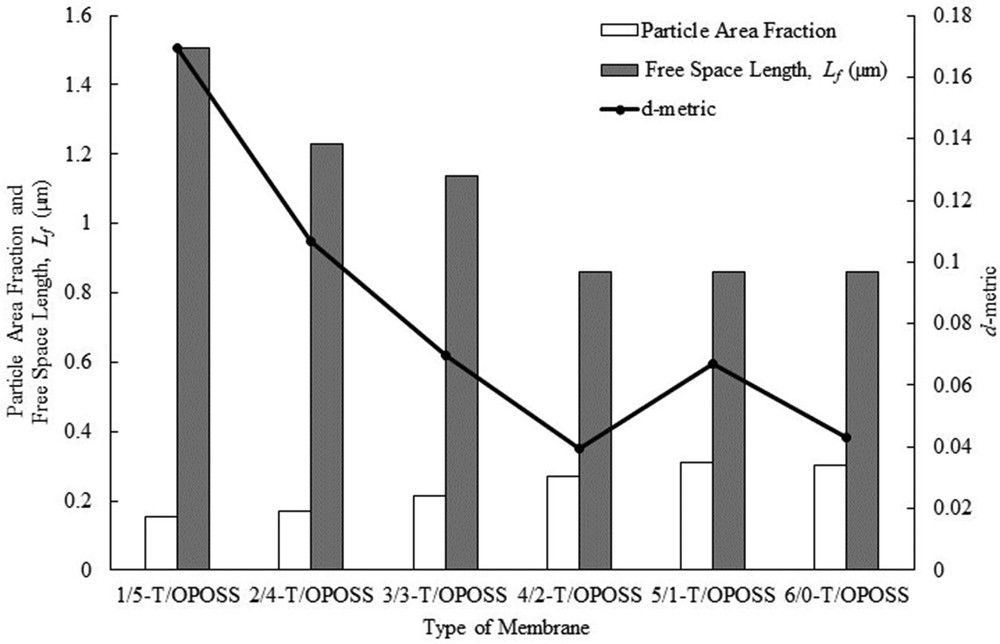
Particle area fraction, free-space length, and d-metric of TiO2-OPOSS/PSf MMMs. MMM, mixed-matrix membrane; OPOSS, octaisobutyl polyhedral oligomeric silsesquioxane; PSf, polysulfone.
In contrast, the Lf value of the MMMs reduced from 1.5077 μm for 1/5-T/OPOSS to 1.1384 μm for 3/3-T/OPOSS, after which it remained constant for the remaining membranes. The larger the Lf value, the larger the size of the unreinforced polymer region, which represents the weak link of MMM due to the absence of TiO2 nanoparticles. 1/5-T/OPOSS MMM has the largest size of the unreinforced polymer region, whereas 4/2-T/OPOSS, 5/1-T/OPOSS, and 6/0-T/OPOSS MMMs have the smallest size of the unreinforced polymer region. This phenomenon shows that the dispersion and distribution of TiO2 nanoparticles improved with increasing TiO2 loading and reduced OPOSS content up to 3/3-T/OPOSS, beyond which there was no significant difference in the dispersion of nanoparticles. According to Khare and Burris [5], the Lf value decreases when particles distribute more uniformly for a fixed filler loading and size. This result is similar to those of the qualitative analyses displayed in Fig. 6, which showed 3/3-T/OPOSS and 4/2-T/OPOSS at optimum OPOSS loading.
From Fig. 8, it was observed that 4/2-T/OPOSS showed the lowest d-metric value, which proved that the TiO2 dispersion and distribution was optimum at 4 wt % of TiO2 and 2 wt % of OPOSS. The lower the value of d-metric, the lesser the particle distribution deviation relative to the hexagonal uniform distribution [6]. With the smallest d-metric value, the size of the unreinforced domain is minimized and the polymer-particle interfacial area is maximized. This means that the filler particles have enhanced dispersion and distribution in the matrix.
In short, octaisobutyl POSS was found to improve the dispersion of TiO2 nanoparticles through qualitative and quantitative analyses. When OPOSS was added into the system, the dispersion of filler particles improved and reduced the particle or agglomerate sizes and at the same time lowered the free-space length and reduced the deviation of particle distribution to that of hexagonal uniform distribution. Based on observations, free-space length technique would yield similar values for the interparticle distance when similar dispersion and distribution patterns were observed. Hence, it is best to use both the characterization tools (free-space length and d-metric) to complement and verify the results obtained.
3.3 Effect of particle dispersion and distribution on gas separation performance
As shown in Fig. 9, the optimum gas separation performance was obtained for 4/2-T/OPOSS MMM which showed the highest ideal selectivity. At this nanoparticles' loading, enhanced dispersion and distribution were obtained, based on quantitative analyses. At this ratio, the TiO2 nanoparticles in the membrane matrix are fully covered with a layer of OPOSS. The caged hybrid framework has two significant roles in improving the TiO2 dispersion and distribution. First, as the inorganic silsesquioxane cage binds with the surface of TiO2, the isobutyl group of OPOSS on TiO2 increased the nanoparticles overall diameter and reduced the surface energy of TiO2 [4,7]. The OPOSS helped to improve dispersion of TiO2 by stabilizing the surface energy of atoms [17]. Moreover, as OPOSS did not react with one another, it acted as a dispersant by replacing the strong contact adhesion force by a weaker noncovalent adhesion force, which caused the nanoparticles to disperse [18]. Hence, addition of 2 wt % of OPOSS addition was adequate to disperse TiO2 nanoparticles in the synthesized MMMs.
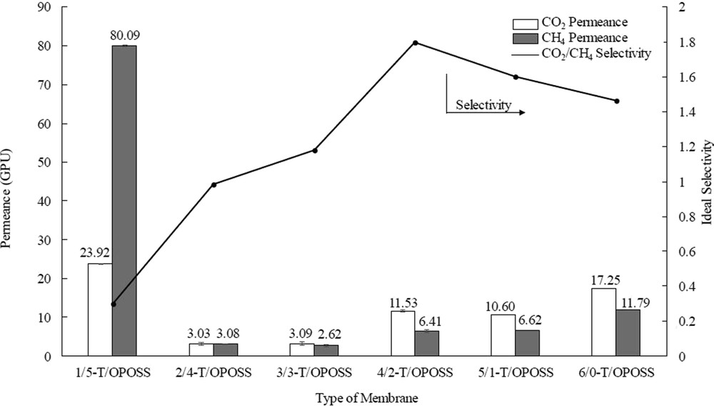
Permeance and ideal selectivity of TiO2-OPOSS/PSf MMMs. MMM, mixed-matrix membrane; OPOSS, octaisobutyl polyhedral oligomeric silsesquioxane; PSf, polysulfone.
In general, the permeance of CO2 was in the range of 3.03–23.92 GPU, while the CH4 permeance was between 2.62 and 80.09 GPU. The selectivity of CO2 to CH4 for the synthesized MMMs was in the range of 0.3–1.8. For 1/5-T/OPOSS and 2/4-T/OPOSS MMMs, the membranes may possess defects (e.g., macrovoids or interfacial defects at the dense selective layer) as the permeance for CH4 was higher than the permeance for CO2 gas. This can be related to the agglomeration of TiO2 as shown in Fig. 5 (a) and (b). The high amount of OPOSS (4 and 5 wt %) did not improve the dispersion of TiO2 nanoparticles instead created macropores and interfacial defects on the selective layer which allowed CO2 and CH4 to pass through. Hence, the ideal selectivity of CO2 and CH4 was rather low. On the other hand, the gas permeance of the remaining MMMs showed increment in the CO2 and CH4 permeance. In addition, the ideal CO2/CH4 selectivity of 3/3-T/OPOSS, 4/2-T/OPOSS, 5/1-T/OPOSS, and 6/0-T/OPOSS were 1.2, 1.8, 1.6, and 1.4 respectively. This is due to the depth of the finger-like structure that increased with the increasing TiO2 nanoparticles loading (Fig. 5). This subsequently increased the porosity of the membrane because of the formation of larger finger-like cavity [15]. Hence, the gas permeance of CO2 and CH4 also increased because of the increment in the membrane porosity.
4 Conclusion
The caged hybrid framework used in this study was found to effectively disperse TiO2 nanoparticles in the membrane matrix of TiO2-OPOSS/PSf MMMs, at specific loading. The loading of TiO2 and OPOSS was found to have a small effect on the membrane morphologies and nanoparticle distribution. The dispersion and distribution of TiO2 nanoparticles were studied using qualitative and quantitative analyses. Based on the qualitative morphology analysis, it was revealed that the MMMs have a thin dense top layer, a long and finger-like substructure from the top extending toward the middle, and a sponge-like bottom structure. TiO2 nanoparticle agglomeration was found even at the lowest TiO2 loading (1 wt %). However, with the use of an adequate amount of OPOSS, TiO2 was found to distribute evenly in the polymer matrix. From the quantitative analysis, it was found that 4/2-T/OPOSS MMM showed the lowest free-space length, Lf and d-metric values, which is in close agreement with qualitative analyses results. Hence, this proved that 4 wt % of TiO2 and 2 wt % of OPOSS was sufficient to enhance the dispersion and distribution of nanoparticles in the membrane matrix. The highest CO2/CH4 selectivity was achieved by 4/2-T/OPOSS MMM because of the enhancement in dispersion and distribution of TiO2 nanoparticle. The dispersing ability of the caged hybrid framework was found to be useful to stabilize TiO2 and potentially other nanoparticles such as magnesium oxide, MgO. To further improve the gas separation performance, different types of polyhedral oligomeric silsesquioxane and their effects as a dispersant can be studied.
Acknowledgements
The authors are thankful to the CO2 Research Centre (CO2RES) under the Institute of Contaminant Management, Universiti Teknologi PETRONAS (UTP), for the experimental and technical support. In addition, the authors would like to express their gratitude for the financial support received from Fundamental Research Grant Scheme (FRGS) Ref. No. FRGS/1/2018/TK02/UTP/02/3, Cost Center 015MA0-003.