

1 Introduction
Visualization and/or crystal defect analysis of deformation microstructures in deformed minerals have been mainly performed using petrological microscopy (of etched dislocations in thin sections), scanning electron microscopy (SEM), and transmission electron microscopy (TEM). The diffraction contrast (amplitude contrast) imaging in TEM is the best to observe individual crystal defects such as dislocations and stacking faults (Hirsch et al., 1977). Orientation-controlled electron channeling contrast imaging in SEM is also a diffraction contrast technique to characterize microstructures such as subgrain boundaries and individual dislocations (Zaefferer and Elhami, 2014).
However, these two electron microscopy techniques have a huge gap between in the specimen preparations and spatial resolutions in the characterization. SEM can be applied into multi-grain textures containing dislocations in a surface-polished bulk sample, while dislocation characterizations in TEM can be performed in a thin foil. In TEM, dislocation microstructures, e.g., partial dislocations and stacking faults, can be characterized intensively in a limited area of the TEM foil. However, the large-scale information, i.e. fabric and multi-grain textures, which can be obtained in the SEM work, is difficult to be addressed in the limited sample volume after the thinning process by Ar-milling or FIB. On the contrary, SEM observation is relatively easy because one has only to prepare a specimen by surface-polishing. The characterization is very powerful to investigate the fabric from a bulk sample preserving the original defects.
“ECCI under controlled diffraction conditions” (cECCI) (Zaefferer and Elhami, 2014) is a powerful method for quantitative microstructural characterization of crystal defects. However, to perform the cECCI, a eucentric five-axe-positioning sample-tilt stage and supporting software (e.g., TOCA program in Zaefferer and Elhami, 2014) to control the desired crystal orientations are mandatory. Recently, an application of orientation-optimized ECCI into rock-forming minerals was reported to characterize individual dislocations in a field emission scanning electron microscope (FE-SEM) equipped with an electron backscatter diffraction (EBSD) system (Miyajima et al., 2018). In the ooECCI, we refine the two-beam condition of a Kikuchi band at the Bragg condition to maximize the visibility of individual dislocations with a Burgers vector. This orientation refinement was successfully performed by using a conventional sample-tilt stage in backscattered electron (BSE) imaging assisted with pre-EBSD measurements. Here we present combined ECCI and FIB milling techniques to prepare site-specific TEM samples for dislocation analysis of deformed single-crystal pyrope-rich garnet and polycrystalline forsterite. The site-specific ECCI-TEM characterizations can provide a new approach to investigate the dislocation microstructures of deformed materials at high pressure and high temperature.
2 Material and methods
2.1 ECCI procedures and conditions in a FE-SEM
The orientation-optimized electron channeling contrast imaging (ooECCI) was employed for the investigation of individual dislocations and forming subgrain boundaries. A conventional field-emission scanning electron microscope (FE-SEM),Zeiss LEO 1530 FE-SEM with the GEMINI column, equipped with an electron-backscatter-diffraction (EBSD) system, was used for ECCI with a backscattered electron (BSE) detector. The acceleration voltage and the beam current are 20–30 kV and 11 nA, respectively. The working distance is 7–10 mm. The detectors were a 120-mm2 annular scintillator-type detector (KE Development CENTAURUS) placed directly under the lens’ polepiece for ECCI (backscattered geometry) and a low-light camera with a phosphorus screen (Nordlys II of Oxford Instruments) for EBSD. Before ECCI, the crystal orientations of single-crystal garnets were determined by using off-line indexing of Kikuchi lines of (hkl) in each Kikuchi pattern acquired with the EBSD camera system. The SFC software (Kogure, 2003) was used for indexing Kikuchi bands to identify crystal planes nearly parallel to the incident beam at the 0-degree-microscope stage (or sample-tilt stage) in the FE-SEM. The detailed procedure for the ooECCI of a large single crystal was described in case 2 for a natural olivine (Miyajima et al., 2018).
2.2 Specimens for ECCI and TEM
The specimens for ooECCI are experimentally deformed single-crystal pyrope-rich garnets. Single crystals of a natural pyrope-rich garnet (Py73Al15Gr12, averaged Z-numbers, AZs 10.4) were deformed at 3.5 GPa and 1273 K in a pure-shear geometry on a multi-anvil apparatus-in house (MAVO 6-ram press; Manthilake et al., 2012). The total strain and strain rate of the M643 and the M633 runs are 0.52 and 8.3·10−5 s−1 and 0.30 and 5.0·10−5 s−1, respectively. The crystal orientations were not controlled in the deformations but, in the M633 run, the single crystal was incidentally forced to be sheared nearly in the <100> direction on the {011} plane.
As a test of the applicability limit of ECCI into low-atomic-number minerals (averaged Z-numbers, AZs ∼ 10) and iron-free minerals, e.g., quartz, a polycrystalline forsterite (Bollinger et al., 2015) was also observed in ECCI. The specimen was deformed in a deformation DIA high pressure apparatus at 5.5 GPa and 1373 K with strain rate = 4.4·10−5 s−1 and stress = 263 MPa. The detailed procedure in the ooECCI of a polycrystalline mineral was described in case 1 for torsion-deformed ferropericlase (Miyajima et al., 2018). All the experimental conditions for each specimen are described in Table 1.
Experimental conditions of the ECCI samples.
| Run number | Pressure (GPa) | Temperature (K) | Total strain | Strain rate (10−5 s−1) | Stress (MPa) |
| Single-crystal natural pyrope | |||||
| M643 | 3.5 (0.5) | 1273 | 0.52 | 8.3 (0.1) | |
| M633 | 3.5 (0.5) | 1273 | 0.30 | 5.0 (0.1) | |
| Polycrystalline synthetic forsterite | |||||
| 69-B | 5.5 (0.1) | 1373 | 4.4 (0.06) | 263 (48) |
2.3 FIB and scanning TEM procedures and the conditions
After the selection of targeted microstructures in the ooECCI, a site-specific TEM thin foil (that we call “TEM lamella” in the FIB session) of pyrope-rich garnet (M643) was prepared with a dual-beam (Ga and field emission electron guns) focused ion beam (FIB) milling machine, FEI Scios, equipped with a sample-lift-out manipulator system, FEI Easylift. The Ga-beam conditions of the trench milling process in the M643 sample are 30 kV for the acceleration voltage and 5–30 nA for the beam current. After cleaning the TEM lamella surface by a 1-nA Ga beam, the lamella was lifted out and glued on a TEM grid by the Easylift system. The final thinning conditions are 30 kV and 300 pA to obtain an electron transparency against a 200-kV accelerating electron beam in TEM. The TEM lamella was milled normal to the main compression axis in the pure shear geometry.
The TEM characterization was performed by using a 200-kV scanning transmission electron microscope, FEI Titan G2 80-200 S/TEM. Crystal defect microstructures in the pyrope-rich garnet were observed in a conventional TEM mode with bright-field (BF), dark-field (DF) and weak-beam dark-field (WBDF) images to characterize dissociated dislocations, stacking faults between short spreading partial dislocations and long stacking fault ribbons. To determine the crystal orientations and diffraction vectors in TEM imaging, selected-area electron diffraction (SAED) was used. The scanning transmission electron microscopy (STEM) mode with BF, DF and high-angle annular dark-field (HAADF) detectors was also employed to obtain a whole view of the TEM lamella on the distributions of defects and chemical homogeneities.
3 Results and discussion
3.1 ECCI of the deformed single-crystal pyrope-rich garnet
Fig. A.1 (multimedia component No. 1) shows the BSE image of a whole view of the deformed single-crystal pyrope-rich garnet (M643). Striped contrasts are visible along the direction from upper left to lower right, which are likely to be a deformation-related feature; we call it “deformation band” because it has no remarkable chemical difference in energy-dispersive X-ray analysis. The contrasts are originated from a small orientation misfit between the band and the matrix (Fig. 1a and Fig. A.1c). The acquired Kikuchi pattern in the EBSD indicates a Kikuchi line (KL) of the (046) plane close to the sample's normal position (Fig. A.2, multimedia component No. 2), which means a two-beam condition for KL(046) (or g = 046 in the TEM technical term) available by an orientation optimization within a few degrees in the sample-tilt system of the FE-SEM. We followed the procedure to find an “inversion of contrast” in the BSE intensity (figs. 9 & 10 in Miyajima et al., 2018). Note that the intensity of the KL(046) band is stronger than that of the other Kikuchi bands close to the sample's normal position. After orientation optimization, dislocation-like contrasts were visible in the deformed single-crystal pyrope-rich garnet by using the ECCI excited with KL(046), which have about 33% of the intensity of the maximum structure factor of KL(400) (Fig. 1b). The kinematical diffraction intensity was calculated based on the electron wave length at 20 kV and a pyrope-end member structure. In comparison, dislocations in the deformed single-crystal pyrope-rich garnet (M633) were more visible in the ECCI excited with the strongest KL(400) in the structure (Fig. 2). A Kikuchi band with a high structure factor of more than 30% of the strongest one was mandatory for performing ooECCI with high quality.
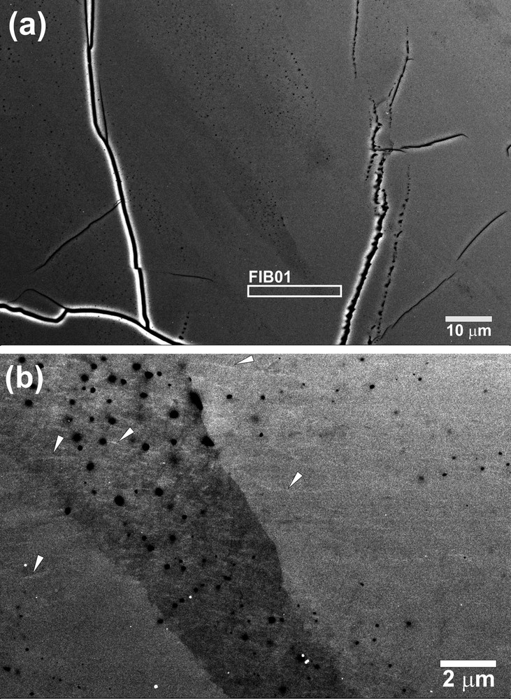
BSE image of a deformation-band (striped) area in the M643 sample: a: at low magnification; a FIB sampling area is indicated by a FIB01-rectanglar square; b: ooECCI with KL(046) (33% of the strongest structure factor) or KL(642) (24%). Some of “dislocation-like” contrasts are indicated by arrowheads. Note that the compression axis and the extension axis were aligned along the vertical direction and horizontal direction in the images, respectively.
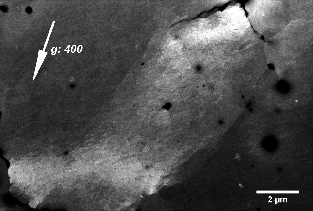
ooECCI of inclined dislocations and subgrain boundaries in the M633 pyrope-rich garnet. The excited Kikuchi line of KL(400) corresponds to one of the strongest structure factors in the pyrope garnet structure, which is about three times stronger than KL(046) at an acceleration voltage of 20 kV. Note that the compression axis and the extension axis were aligned along the vertical and horizontal directions in the images, respectively.
3.2 TEM of the deformed single-crystal pyrope-rich garnet: TEM confirmation of the dislocation microstructures and implications
In the TEM on the M643 sample (Fig. 3), dislocation microstructures with dissociated dislocations and stacking fault ribbons were confirmed, which correspond to the dislocation-like contrasts in the ooECCI image (Fig. 1b). The microstructure in TEM is very complicated, and thus the stacking fault fringes (ribbons) are profuse and curved (Fig. 4). The dark field TEM image with excitation error, s = 0 (Fig. 4c) was better to visualize the stacking fault ribbons than weak-beam dark-field TEM image (Fig. 4a and b). The defects might be a super-partial dislocation and its movement can drag antiphase domain boundaries (APBs) between partial dislocations. Current TEM characterizations using diffraction vectors g = 400 and 444 indicated that all the dislocations are visible and curved and elongated along the
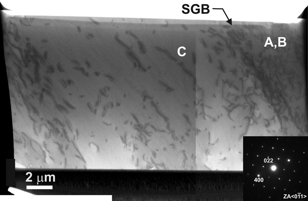
BF-STEM image of an overview of the TEM lamella from the deformation band area (indicated in the Fig. 1) in the M643 sample. A high density of individual dislocations in the deformation band forms a subgrain boundary (SGB) in the M643 sample. A vertical line in the central part of the image is an artefact in conjunction with two scanning images. The inset indicates the nearest zone axis of

DF-TEM images of dislocation microstructures in the deformation band (indicated as A, B and C areas in Fig. 3): a: DF image with g = 400 (s > 0); b: WBDF-TEM image with g = 444 (s >> 0). Short dissociations are visible. The long arrowhead (center) indicates the same dislocation in the both images of (a) and (b). The triangles indicated strain-free bubbles or precipitates; c: DF-TEM image with g = 400 (s = 0). Wide dissociations with long stacking fault ribbons are visible. The inset indicates the nearest zone axis of
DF-TEM images of dislocation microstructures in the deformation band (indicated as A, B and C areas in Fig. 3): a: DF image with g = 400 (s > 0); b: WBDF-TEM image with g = 444 (s >> 0). Short dissociations are visible. ... Lire la suite
The dislocation microstructures might be also related to high water activities in the deformation. Some dislocations interact with strain-free bubbles like deformed wet-quartz (McLaren et al., 1989) or precipitates (Voegelé et al., 1999) (Fig. 4b). Although we did not investigate water activity on the natural garnet by infra-red spectroscopy, high water activities in pyrope-rich garnet under high-pressure and high-temperature conditions were reported by Mookherjee and Karato (2010). The dissociated <110> dislocations into 1/n <110> partial dislocations with widely spreading stacking fault ribbons were also reported in low-temperature eclogitic garnets with some potential water activity (Voegelé et al., 1998). The unusual stacking fault ribbons might be related to low-stacking-fault energy in hydrous and high-temperature-deformation conditions of a natural almandine garnet (Smith, 1982; Smith, 1985). Further characterization of the complex dislocation microstructure sheds light on the deformation mechanisms of pyrope-rich garnets in the Earth's mantle.
3.3 ECCI of a deformed forsterite. Application into iron-free rock-forming minerals
For further application, we tested the ooECCI method with an iron-free forsterite from the deformation experiments at high pressure and high temperatures (Bollinger et al., 2015). Some of the forsterite grains with internal sub-grain boundaries are clearly observed in a BSE image at low magnification (Fig. 5a). An ooECCI image of one of the grains displayed individual dislocations (Fig. 5b). The visibility of individual dislocations in forsterite strongly supports potential applications of ECCI into iron-free high-pressure polymorphs. Note that ECCI of dislocations in forsterite denies the necessity of iron decollation and enrichment on dislocations due to pipe diffusion and Cottrell atmosphere in natural processes, when we try to observe individual dislocations in the mantle olivine by using ECCI. The ooECCI of individual dislocations in iron-bearing minerals (Miyajima et al., 2018) is not a composition-dependent BSE imaging, but an orientation-contrast microscopy.
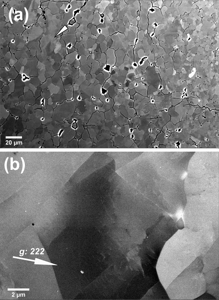
ECCI of a deformed forsterite: a: polycrystalline textures at low magnification; b: ooECCI of the grain indicated by an arrowhead in (a). The excitation with KL(222).
4 Conclusions
The ooECCI provides dislocation microstructures of pyrope-rich garnet and forsterite recovered from deformation experiments at high pressure and high temperature. To our knowledge, it is the first time one observes individual dislocations in silicate garnet by using FE-SEM, which is confirmed by site-specific FIB sampling and TEM characterizations. The resolution of the ECCI on a bulk specimen is lower than that of TEM on an ultra-thin foil, but ECCI allows us to investigate dislocations across subgrain boundaries and over grains on the bulk deformation specimen. With the advantages in the ECCI work, we can select a target of deformation textures at the micrometer scale for further TEM characterization. Also, before proceeding with TEM, we can perform additional annealing experiments of the same bulk specimen to study dislocation recovery processes. Thus, the analytical procedure from ooECCI to site-specific FIB-sampling might be a standard for our high-pressure community to characterize individual dislocations in TEM. It serves as an alternative to the conventional way from a petrological thin section to the Ar-milling method to perform the TEM characterizations on deformed samples under high-pressure conditions.
Acknowledgments
We thank R. Njul for his support of preparation of polished specimens and D. Wiesner and U. Trenz for the FE-SEM work. F. Heidelbach gratefully acknowledges financial support through DFG grant He3258/2-1. We acknowledge the DFG for funding of the FIB facility (grant INST 91/315-1 FUGG) and the TEM facility (grant INST 91/251-1 FUGG). Part of this research, deformation of forsterite, was supported by the Consortium for Materials Properties Research in Earth Sciences (COMPRES) under NSF Cooperative Agreement EAR 06-49658, as well as the “Agence nationale de la recherche” (ANR) Grant BLAN08-2_343541.