

1 Introduction
Many renewable sources of energy, such as wind power and solar energy provide energy in a fluctuating manner. Electrical energy storage (EES) is one of the possible solutions [1]. EES can potentially smooth the variability in power flow from renewable generation and store renewable energy in order to decrease the cost of integrating renewable power in the electricity grid, increase market penetration of renewable energy, and lead to greenhouse gas (GHG) reduction [2].
A new approach to seasonal storage of renewable energy is based on using excess electricity produced from a renewable source to co-electrolyze at high temperature (1073 K) steam and CO2 into syngas via a reversible solid oxide cell (RSOC) in solid oxide electrolysis cell (SOEC) mode. The syngas produced (H2 + CO) is fed into a methanation reactor where it is converted into CH4. This gas is then injected into the natural gas network. When high-consumption peaks appear, the RSOC is switched to solid oxide fuel cell (SOFC) mode fed by syngas. The latter is produced by tri-reforming of methane. The diagram of this process is described in Fig. 1 and detailed in [3].
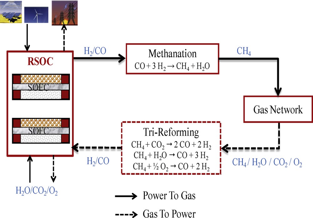
(Color online) Diagram of the power-to-gas process.
The main conversion step in such process is methanation. Production of synthetic natural gas (SNG) from carbon monoxide and hydrogen is described by the CO methanation reaction (Eq. (1)):
| (1) |
Another reaction called water gas shift (WGS) occurs simultaneously whenever active catalysts are used:
| (2) |
The heterogeneously catalyzed methanation is important in two main applications: removal of traces of CO in hydrogen-rich gases for the ammonia synthesis and the conversion of syngas to methane-rich fuel [4,5]. This reaction was performed on various catalysts: ruthenium (Ru), rhodium (Rh), platinum (Pt), iron (Fe), nickel (Ni), and cobalt (Co) [6]. Nickel catalyst is the most appropriate because of its selectivity, activity, and price.
Unfortunately, the commercial deployment of technologies for the production of SNG is constrained by economic and technical barriers. The main issue of methanation is the strong exothermicity of the methane formation reactions. The temperature increase may cause catalyst sintering and possibly lead to carbon particle formation. One pilot plant was designed by Lurgi and Sasol in Sasolburg (South Africa) and another pilot plant was developed by Lurgi and El Paso Natural gas Corporation in Austria [7]. Based on the results of Lurgi and Sasol, the first and only commercial unit has been developed in the USA (North Dakota) in 1984, producing 1.53 billion Nm3/year [8,9]. This process is composed of an isothermal reactor and two adiabatic fixed bed reactors with recycling [10].
The TREMP™ process (Topsoe's Recycle Energy-efficient Methanation Process) was developed by Haldor Topsoe's laboratory. Due to the unique MCR-2X methanation catalyst, TREMP™ can operate at high temperature, up to 973 K. This catalyst allows reaction heat recovery in the form of high-pressure superheated steam and low recycle ratio to ensure energy saving [11]. CO methanation takes place in adiabatic fixed bed reactors. The reaction exothermicity results in a high temperature increase. Recycling is used to control this temperature rise in the first methanation reactor [12]. No industrial facility has been developed because of the political problems and the price of energy [7,13]. However, within the last five years, the interest in substitute natural gas has become strong. Efforts have been reinitiated in the technology, and the knowledge gained over the years has been used to refine the tried and tested technology and catalyst [13]. As a result, an updated version with improved efficiencies and lower investment cost is now being offered to the market [14].
In Scotland, a demonstration plant (Westfield Coal Gasification plant) was built, producing 2.46 million Nm3/h of SNG from coal. The methanation unit composed of fixed bed reactors with gas recycle was added to an existing Lurgi–Rectisol purification unit [7].
A further development of the British Gas Corporation was the HICOM process, in which shift and methanation are combined. The syngas is passed through a series of fixed bed reactors with recycling of reacted gas and steam dilution [7,8].
In Germany, Linde developed an isothermal fixed bed reactor with indirect heat exchange [15]. The reactor itself is able to produce steam from the heat of the exothermic methanation reaction. A part of the steam is added to the syngas mixture to minimize the risk of carbon deposition, before being fed into the isothermal and adiabatic methanation reactors [7].
All processes described above use fixed bed reactors with recycling of the cooled product gas and/or adding steam to limit the strong exothermicity of the reaction. Monitoring temperature increase can be ensured by recycling of reacted gas or steam dilution, or by special technologies, such as isothermal reactors or fluidized beds, each one with indirect cooling by evaporating water [16–18].
The aim of this study is to model and simulate the syngas-to-methane process accommodated in an isothermal fixed bed reactor for renewable electricity storage. The methanation reactor model incorporates the catalytic reaction kinetics. The simulation results will be compared with experimental data obtained on commercial Ni-based catalysts for CO methanation reported in the literature for the model validation. Then, a sensitivity analysis will be carried out in order to evaluate the effect of temperature, pressure, and CO2 addition.
2 Methodology
2.1 Model implementation
The simulation model was developed using Aspen Plus™. The used physical properties of the following compounds are provided by Aspen Plus™: water (H2O), carbon dioxide (CO2), methane (CH4), hydrogen (H2), and carbon monoxide (CO).
For the thermodynamic model, the RKSMHV2 is used. The RKSMHV2 property method is based on the Redlich–Kwong–Soave equation of state with modified Huron–Vidal mixing rules. This model is used for mixtures of non-polar and polar compounds, in combination with light gases [19]. All the binary interaction parameter values needed for this model were provided by Aspen Plus™ library.
An isothermal fixed bed reactor is modelled as an ideal plug flow reactor (PFR). An isothermal reactor presents many advantages over an adiabatic methanation reactor: product recycling may be reduced and one pass operation at high concentration is practical, heat exchange duties and cooling costs are lower, avoiding extremely high reactor exit temperatures and hot spots prevents sintering of the catalyst, thereby preserving the catalyst's life and the need for internal refractory insulation as normally used for high temperature adiabatic methanation reactors is eliminated (this is also a cost-saving procedure) [20].
Assumptions considered in the model are:
- • the system is in steady-state conditions;
- • axial heat and mass transfer are assumed to be negligible;
- • the reactor operates in isothermal conditions. As a result, the hydrodynamic parameters of the bed, the physical properties of components and the reaction rate constants are considered to be constant throughout the bed;
- • coke formation is neglected.
2.2 Kinetic scheme
The methanation reactor model is based on kinetics developed by Kopyscinski et al. [21] over a commercial catalyst Ni/Al2O3 (50 wt% Ni/Al2O3, BET surface area = 183 m2/g) in a fixed bed reactor.
The rate equations follow the Langmuir–Hinshelwood approach (Eq. (3)) by the assumption of the rate-determining step (RDS) for the reaction mechanisms proposed by Kopyscinski [7]:
| (3) |
This elementary step is considered as being the slowest reaction step and as being responsible for the overall rate. The assumed RDS for the methanation and water gas shift rate equations (Eqs. (5) and (6) in which pressures are expressed in bar and temperature in K) is:
| COH* + H* → –CH* + OH* | (4) |
All other reaction steps are regarded to be in equilibrium or irreversible. The derivation of the rate equations takes the surface coverage of the relevant adsorbed species into account. The resulting rate equations include the driving force in terms of partial pressure of the gas phase species and the adsorption term, which summarizes the retarding effects of the adsorbed reactants and products.
The surface coverage of the reactants and products are calculated for equilibrium adsorption of the considered species; by that, the rates of adsorption and desorption are the same. More details about the methodology and the hypotheses used to get the kinetic rate equations are reported in reference [7].
For the CO methanation reaction:
| (5) |
For the WGS reaction:
| (6) |
Rate constants (k1 and k2) for the above equations are defined as a function of temperature:
| k1 = 3.34 × 10⁶ exp (mol/kgcat·s) | (7) |
| k2 = 9.62 × 10¹⁴ exp (mol/bar1.5kgcat·s) | (8) |
KOH and Kc are constants related to surface adsorption in equilibrium, which are functions of the temperature.
| KOH = 3.97 × 10⁻⁷ exp (bar−1/2) | (9) |
| Kc = 8.1 × 10⁻⁶ exp (bar−1) | (10) |
| Ka = 9.3 × 10⁻² exp | (11) |
Keq is the equilibrium constant of the water gas shift reaction:
| Keq = exp | (12) |
Pre-exponential factors of the kinetic rate and adsorption coefficients as well as the corresponding activation energies and adsorption heats were taken from [7]. The thermodynamic equilibrium constant of WGS reaction (Eq. (12)) is given by [4]. This kinetic model is valid within a temperature range between 473 and 673 K. Based on the electrolysis output, the molar ratio of H2 to CO is greater than 3. Under these conditions, coke formation is lower. The pressure drop along the PFR reactor is calculated by the Ergun momentum balance equation (Eq. (13))
| (13) |
P: the pressure (Pa)
Z: the reactor length (m)
μg: the linear velocity of fluid phase (m/s)
μ: the effectiveness factor used for the intraparticle transport limitation (–)
dp: the particle diameter (m)
ρ: the density of catalytic bed (kg/m3)
ɛ: the void fraction of the catalytic bed (–)
In this work, the methanation reactor not only converts syngas into methane, but it also provides the steam needed for electrolysis and heating or for generating electricity by using a steam turbine. This method allows increasing the global efficiency of the electricity storage process [22]. In addition, the use of water as a coolant helps to control the temperature of the process gas within the desired limits [23].
3 Results and discussion
3.1 Model validation
In order to validate the proposed model, a comparison of experimental data with the results simulated by the present model was performed.
Fig. 2 shows the simulation results of gas concentration profiles compared with the experimental one. This latter is provided by Kopyscinski [7] at 633 K, 0.2 MPa and H2/CO = 5.
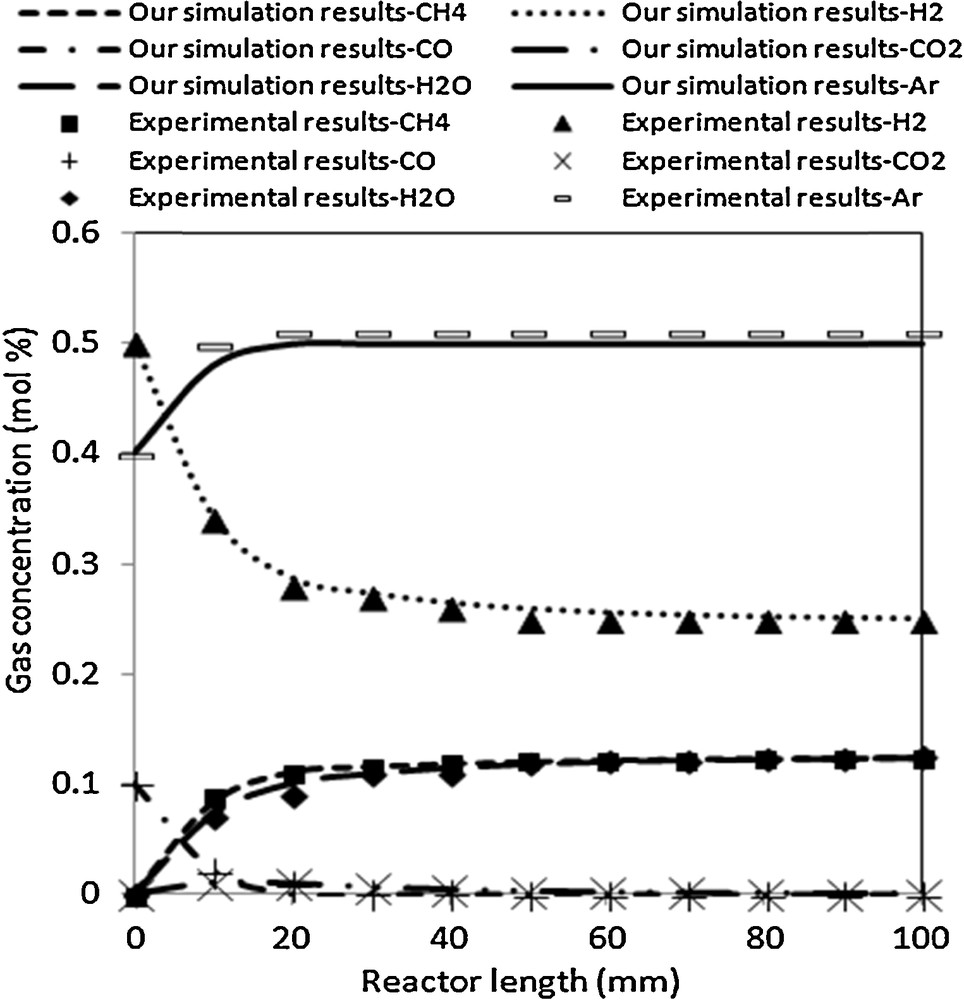
Simulation results compared to experimental data at 633 K, 0.2 MPa and H2/CO = 5.
The predicted model results are in good agreement with the experimental data. At 633 K, the rate of disappearance of H2 decreases, CO is completely converted at the end of the reactor, and the rates of formation of H2O and CH4 increase. The concentrations of CH4 and H2O at the outlet reach almost the equilibrium concentration of 12.5 mol% for CH4 and H2O. The concentration profiles show at first a slight increase of CO2, which passes through a maximum and then decreases again. The increase of CO2 is due to the water gas shift reaction. Indeed, the concentration of H2O is less than that of CH4 when CO2 increases. As soon as the CO concentration is below 1 mol%, the CO2 concentration decreases as well. This is explained by the fact that the conversion of CO occurs almost exclusively by hydrogenation to CH4 and H2O. As the concentration of H2O increases, the water gas shift reaction becomes important and leads to the formation of small amounts of CO2. The dominant route for CO disappearance is still methanation. When the concentration of CO reaches a level below the equilibrium value of the water gas shift reaction, the reverse water gas shift occurs because there is still a high concentration of H2 present [7]. This leads to a decrease of the CO2 concentration and to an increase of the H2O concentration to a value again equal to the CH4 concentration at the end of the reactor.
Based on the output of SOEC in the renewable electricity storage process, a parametric study was conducted to evaluate the effect of temperature, pressure and CO2 on the outlet gas composition. Table 1 shows the inlet gas composition and the operating conditions.
Inlet gas composition and operating conditions.
| Inlet gas composition (mol. %) | |
| H2 | 59.89 |
| H2O | 14.81 |
| CO | 20.03 |
| CO2 | 5.27 |
| Temperature (K) | 593 |
| Pressure (MPa) | 0.4 |
3.2 Effect of temperature
As shown in Fig. 3, at 543 K, H2 and CO react to produce CH4 and H2O. The molar fractions of H2 and CO decrease from 46% to 20% and from 15% to 5%, respectively. The molar fractions of CH4 and H2O are almost equal and reach 30% and 32%, respectively. The presence of equimolar amounts of CH4 and H2O, as well as the small amount of CO2 produced, means that the WGS reaction is negligible below 543 K.

Effect of temperature on outlet gas composition at 0.4 MPa and H2/CO = 3.
Although the reaction is exothermic and therefore thermodynamically favoured at low temperatures, Fig. 3 shows that CO conversion is low below 550 K. This is due to the fact that the catalyst used is not active enough at low temperatures. However, at higher temperatures, CO and H2 conversions increase, which is in good agreement with the results of Zang et al. [24].
From Fig. 3, it can be also observed that in a temperature range between 563 K and 573 K, the molar fractions of CO2 and H2 increase, and CO is completely converted. The increase of CO2 is mainly due to the WGS reaction accompanied by water consumption and hydrogen production. Finally, it can be seen that the molar fraction of H2O decreases when the corresponding molar fraction of CO2 reaches a maximum value of 14% at 573 K.
3.3 Effect of pressure
In the present work, the total reaction pressure varied from 0.1 to 1.5 MPa. Fig. 4 displays the pressure dependencies of CO conversion and CH4 production in methanation reaction at 593 K and H2/CO molar ratio of 3. A higher pressure (above 0.4 MPa) leads to higher CO conversion and CH4 production at the same reaction temperature. At 0.4 MPa, the CH4 molar fraction increases from 34% to 38%.
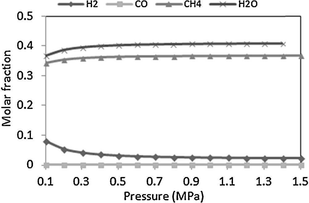
Effect of pressure on outlet gas composition at 593 K and H2/CO = 3.
According to the literature [20,24,25], above 673 K, the pressure has a major effect on catalyst deactivation. In our study, we used an isothermal reactor at 593 K. Therefore, working at pressures of about 0.4 MPa is acceptable. However, in the case of an adiabatic reactor, increasing the pressure over 1.5 MPa is needed to limit the risk of coke deposition.
3.4 Effect of CO2 addition
At the output of the co-electrolysis, there is an amount of CO2 that has not reacted, so this gas can impact the methanation reaction. Thus, the influence of CO2 on methanation was investigated by varying the amount of CO2 in the feed gas from 0% to 13.5% in a temperature range from 553 to 640 K. Fig. 5 illustrates the evolution of CO conversion depending on the temperature and the amount of CO2. It can be seen that at temperatures below 570 K, CO conversion is slightly affected by CO2 addition. Also, at higher temperatures, CO2 does not retard CO conversion. According to the literature [7,24,25], CO2 does not affect the rate of CO conversion; it has rather a positive effect due to the reverse water gas shift, which leads to the formation of additional CO. It can be concluded that at 593 K and a H2/CO molar ratio of 3, CO is completely converted and CO2 has no effect.

CO2 and temperature effect on CO conversion at 0.4 MPa and H2/CO = 3.
4 Conclusion
Producing methane from renewable energy enables bi-directional linking of power and gas network and represents a competitive seasonal storage option. In this work, an isothermal fixed bed reactor of methanation is modelled using Aspen Plus™ software to convert syngas produced by co-electrolyzing steam and CO2 into methane. The comparison between the model results and the experimental data indicates that the proposed model can predict the methanation reactor performance with a good accuracy. The effect of temperature [520–600 K], pressure [0.1–1.5 MPa], and CO2 addition were investigated. The results indicate that at temperatures below 540 K, the WGS reaction is negligible and CO conversion is slightly affected by CO2 addition. At 600 K and higher pressures, the maximum of CH4 production is reached.
Acknowledgment
This work was partially supported by the French National Research Agency (ANR) through the “Systèmes énergétiques efficaces et décarbonés (SEED)” Program (project DEMETER) ref. ANR-11-SEED-0005-02.